The TurboGrafx-16 and original PC Engine do not have RGB, s-video, or even composite video output. However, RGB, composite video, and audio are available through the extension ports on the back of the consoles or directly off the chips. All of these signals require amplification to proper levels before they can be used, though. Tim Worthington’s AV Driver is a general purpose mod that can be used to amplify the video, audio, and sync levels. This install guide describes the process for installing the AV Driver into a US TurboGrafx-16. Note: There is also a video version of this guide, but some of the information in the video is incorrect and has been updated here.
Tools
- Soldering iron
- 4.5 mm game bit
- Phillips screwdriver
- Drill
- Drill bits
- Solder pump, wick, or desoldering iron (optional)
- Files
- X-acto knife
Materials
- AV Driver
- 8-pin mini DIN jack or similar
- Solder
- Thin wire (ribbon cable works well for this)
- Double-sided poster tape
Procedure
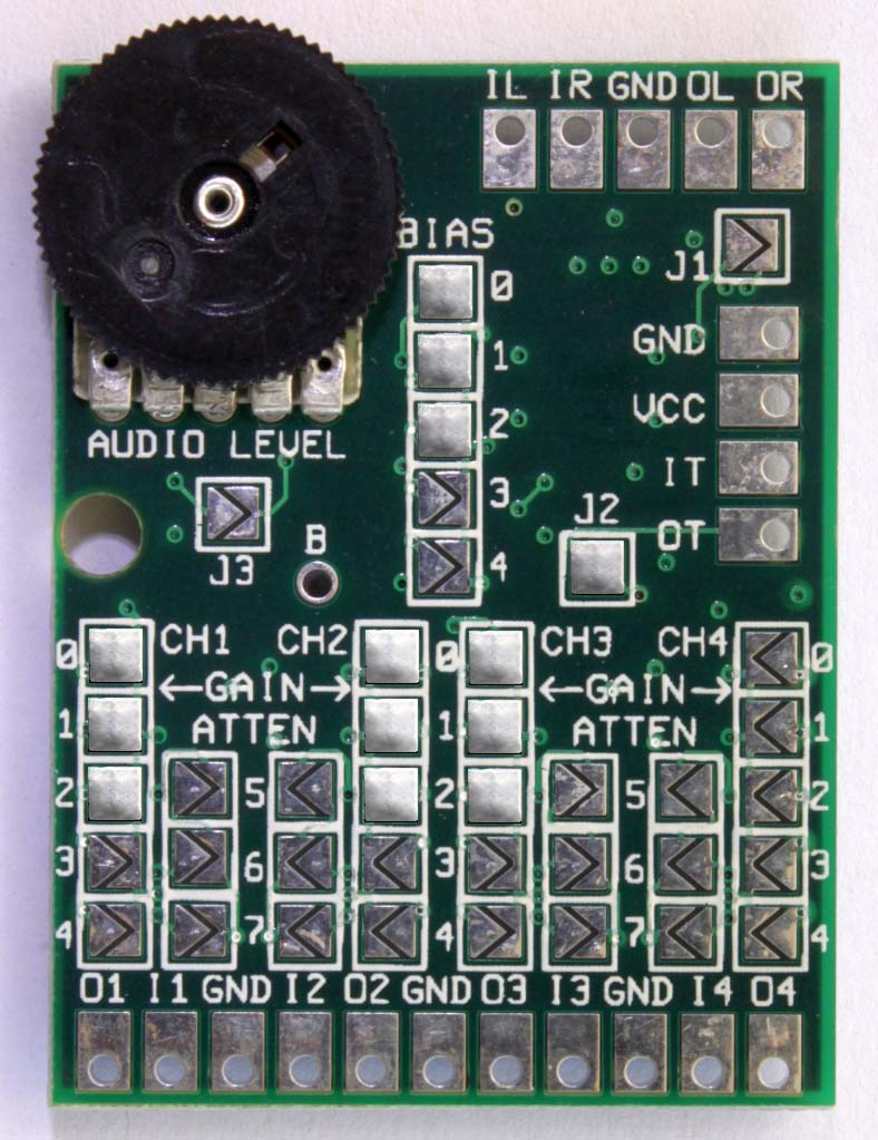
Before even opening the console, set the jumpers on the AV Driver as shown. J1 and J2 are used for setting sync, so you only need to worry about these if you will be using c-sync instead of composite video as sync. J1 is left open since the sync input is lower than TTL level and J2 is closed to provide 75-ohm sync at the output. J3 is left open to enable audio pop suppression, which helps protect your equipment. Finally, the gain and bias jumpers must match, so close the 0, 1, and 2 jumpers for each to get proper signal video signal levels. Note that only three of the four video channels are used, so the remaining jumpers can be left open.
Follow the TG16 disassembly guide to gain access to the motherboard, then choose where you want to install the AV Driver. Placing it behind the expansion port allows for easy connection to the pins of the expansion port, short cable runs, and jack installation in the back. Placing it under the HuCard slot requires longer cable runs but is otherwise more convenient for jack installation on the side of the TurboGrafx-16. Once you’ve chosen a location, use the poster tape to secure it to the motherboard. I recommend using a few stacked pieces to give the AV Driver more distance from the TG16 motherboard to reduce interference.
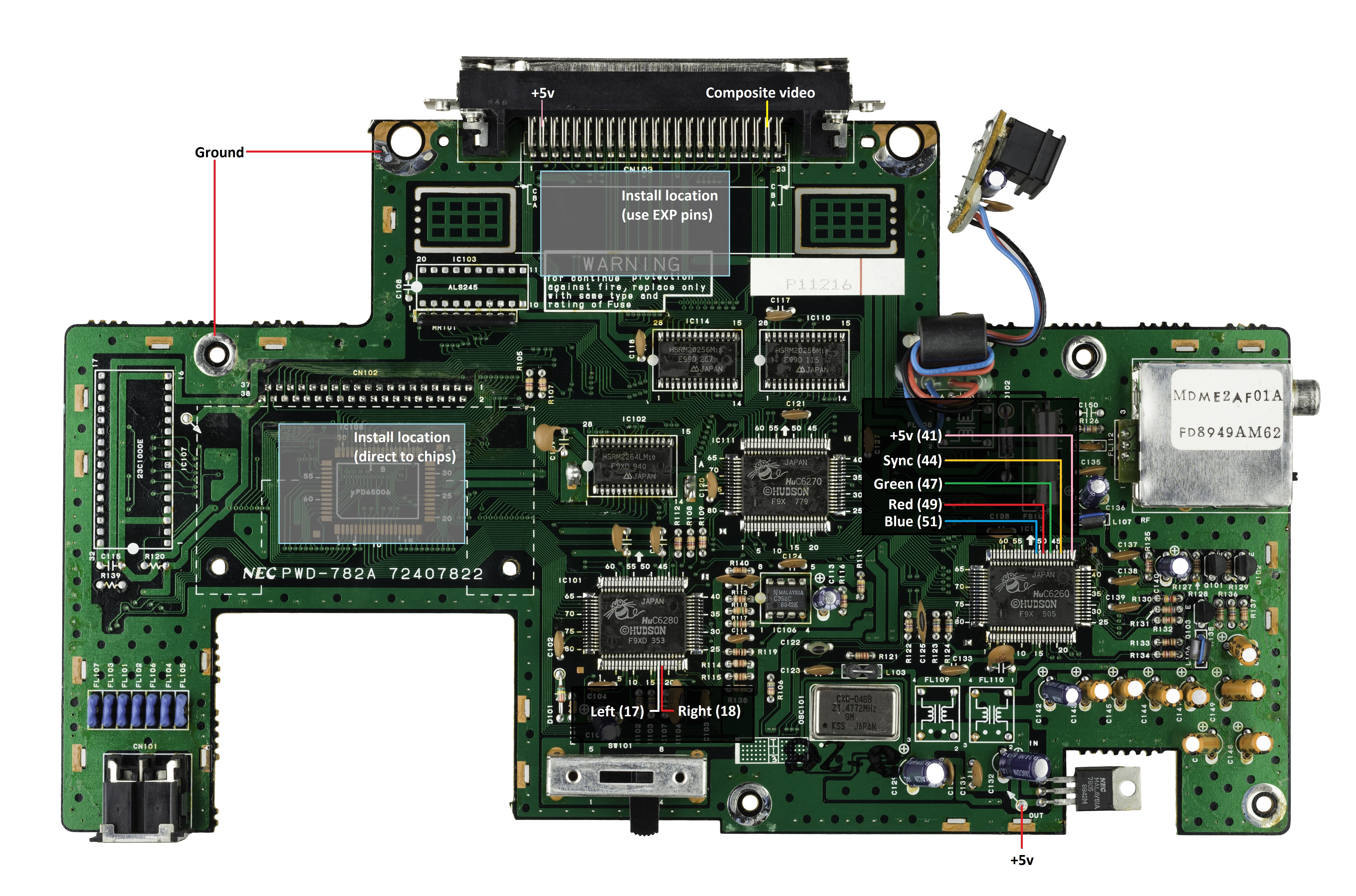
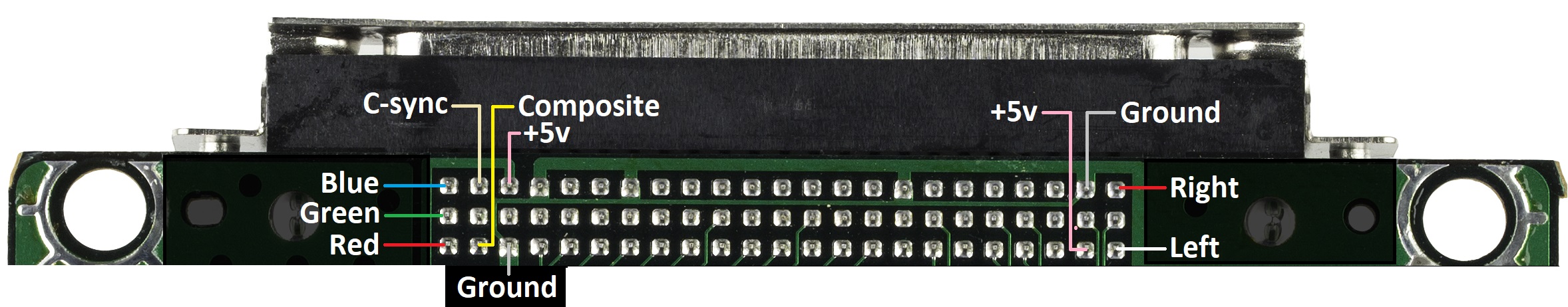
The top image shows where to connect your wires on the top side of the motherboard when connecting directly to the HU6260 and/or HU6280. The bottom image shows where to connect wires on the expansion port pins. Choose whichever is more convenient for you, though I generally recommend using the expansion port option as you are less likely to pull up critical traces by accident. If you are using composite video for sync, you will need to pull this from the expansion port. Pulling power and composite video from the top of the board may help reduce interference by keeping the wires away from other signal lines, so I have also indicated those connections.
Connect the wires to the AV Driver. The video lines (red, green, and blue) from the motherboard connect to the I1, I2, and I3 pads along the bottom. Keep track of which video line is connected to which pad. Connect wires to O1, O2, and O3 pads along the bottom, but leave these loose for now as they are the video outputs and will be connected to the RGB jack later. Again, remember which video line is connected to which pad so you don’t get them mixed up later.
You can connect the ground wire to any of the pads labelled GND. Connect the +5v wire to the VCC pad. The c-sync wire (if you are using c-sync) connects to the IT (sync input) pad. You will also need to connect a loose wire to the OT (sync output) pad to be used to send the c-sync signal through the RGB jack. Connect the left audio wire to the IL (left audio input) pad and right audio wire to the IR (right audio input) pad along the top. Connect loose wires to the OL, OR, and GND pads to be used to connect audio and ground to the RGB jack.
Figure out where the jack will be and cut/drill the hole for it. I chose the side opposite the power jack on the back since the cable won’t stick so far out there. If you took out the RF modulator, that might be the best place to install the jack. How exactly you do this is up to you, but I used a blade to cut a square hole and a drill to drill the holes for the bolts. I also had to remove some material from the jack housing and the case itself to make sure it fit. Just make sure that you can actually close the console back up when you are done.
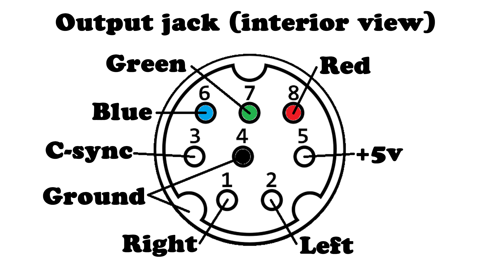
Wire up the RGB jack as shown. This is the view from the inside portion of the jack. Note that you do not need to connect 5v power to the jack, so you can leave that open. If you are using composite video as sync, connect that directly from the TG16 EXP port to the pin labeled c-sync on the RGB jack.
Place the back (technically the top) shield in place and replace the screw that attaches the regulator to the heatsink. Do not solder the shield in place yet. Plug everything in and make sure it works. This is also a good time to set the audio output level. A little bit shy of all the way up seems to be about right, but you can compare it with your other consoles to make sure it is about the same. Once you are certain everything works, solder both shields to the motherboard and reassemble the console.
