Systems that have an AV out instead of RF have a few different RGB options. Note that none of these amplify the audio, so they are not appropriate for the original PC Engine or the TurboGrafx-16. Probably the two most popular are Voultar’s kit or Mickris’s kit. The only real difference between the two is that Voultar’s kit amplifies sync whereas Mickris’s board only amplifies the RGB signals. There are pros and cons to both:
- Voultar’s board gives you the cleanest sync since it is outputting a c-sync signal. However, this requires you to disconnect composite video from the output jack, so you must use RGB.
- Mickris’s board doesn’t deal with sync at all, so you will need to use composite video as sync. This means that you don’t get an isolated sync signal, but you retain the ability to use composite video. However, with a fully shielded cable, the results should be nearly identical to pure c-sync.
Whichever option you choose, the install procedure is basically identical. Note that the procedure below applies to the CoreGrafx consoles. For Duo systems, there’s a nice video from Voultar describing the process.
Tools
- Soldering iron
- 4.5 mm game bit
- Phillips Screwdriver
- Solder pump, wick, or desoldering iron
- Flush cutters or other snips
- Marker
Materials
- RGB mod (see above)
- 8-pin DIN jack (can be ordered here if not included with mod)
- Solder
- Thin wire and/or ribbon cable
- Double-sided poster tape
Procedure
Prepare your RGB mod by covering the underside with electrical tape, then add some non-conductive mounting tape so that you can secure the mod to the motherboard.
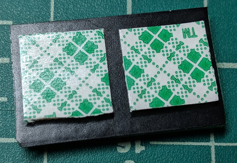
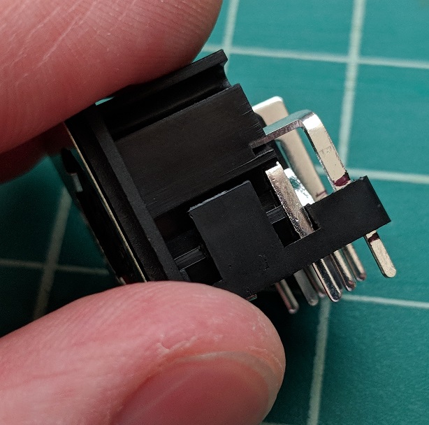
On the new DIN jack, you will need to cut the three rear pins so that it fits in place of the stock jack. If you are going to be using c-sync instead of composite video, you will also need to cut the composite video pin located on the right side of the jack (when viewed from the back). Mark the pins on either side of the plastic housing as shown to help guide you with where to cut.
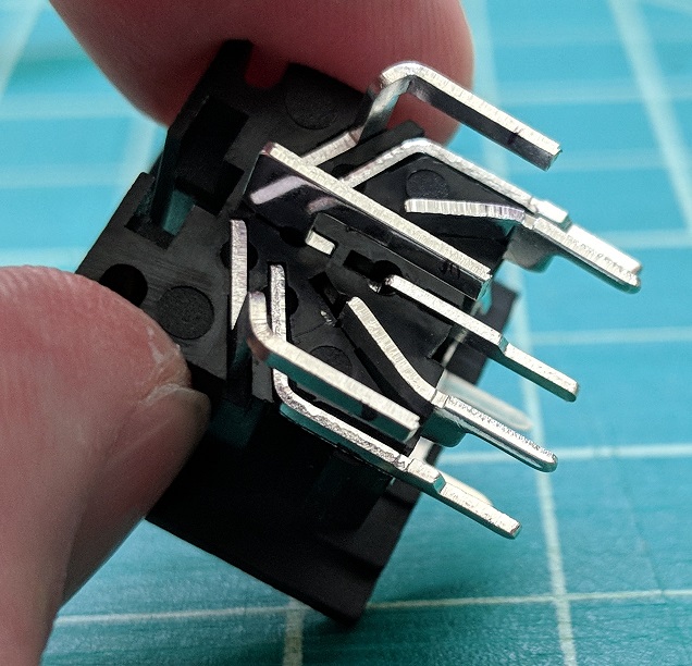
Remove the bottom by pulling out on the clips on either side of the housing. With the pins free of the bottom, cut between the lines you marked in the previous step. This will allow the pins to rest in the housing without touching the circuit board. When you pull the bottom off, the front two ground pins (the thin ones) will probably fall out. If not, remove them as we will be reusing the stock ones instead.
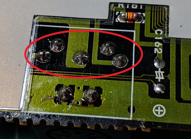
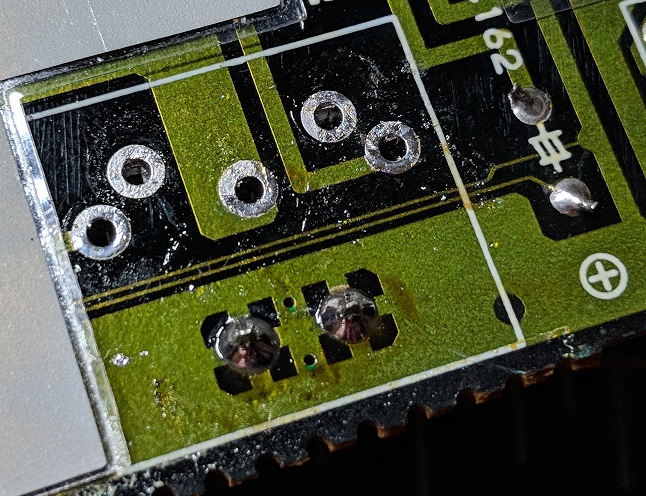
Leave the bottom of the DIN jack off and (carefully) set the jack aside for now. Follow the PCE/TG16 disassembly guide to gain access to the motherboard of your console. Once you have the console open, find the existing DIN jack. Using whatever desoldering tools you have available, desolder the five rear pins of the jack. These are circled in the picture below. Leave the front two in place as they will be reused.
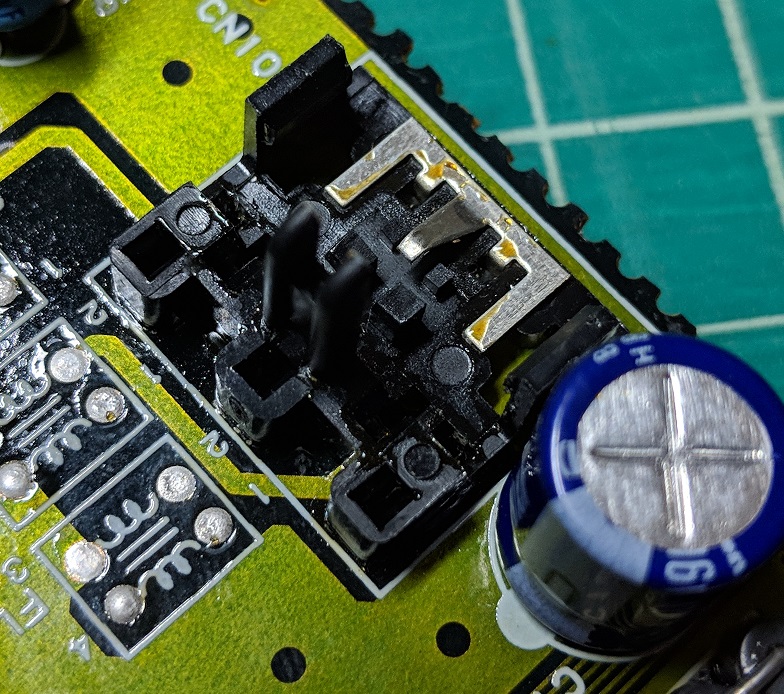
Just like you did with the new DIN jack, unclip the bottom of the housing from the top for the stock DIN jack. Be careful not to break the clips as we will be reusing the bottom. Pull up to remove the jack from the motherboard. This should leave you with the bottom housing and the two ground pins attached to the motherboard as shown in the second picture. Note: if you have a good desoldering iron, it may be simpler to desolder all of the pins and remove the jack as one unit and swap the ground pins outside of the console. Since I do not, this method was easier.
Install the new 8-pin DIN. It should fit right onto the stock bottom piece. Make sure to push it all the way down so it clips in place, then solder the pins on the underside to secure it.
Choose a location for the new bypass board. You will want to put it somewhere that it will not pick up interference from other components (like the chips or oscillator). In this example, Mickris’s board fits nicely behind behind the DIN jack of the CoreGrafx. Stick it in place using the mounting tape.
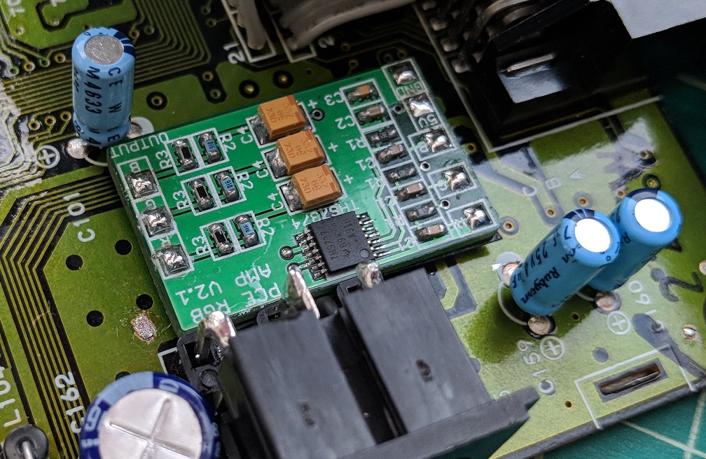
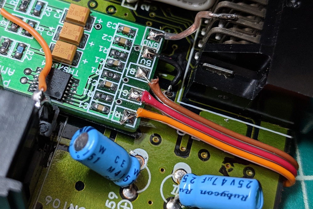
Solder wires for power and ground. Note that power is taken from a small via. You will need to scrape off some varnish/solder resist protecting this via in order to solder to it. Ignore the other wires for now.
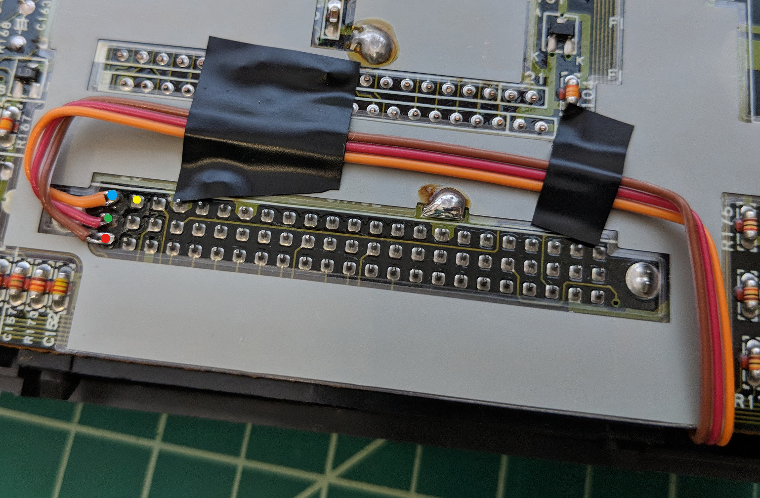
On the underside of the board, solder wires to these pins for RGB and, if applicable, sync (yellow dot indicates sync location). Route the wires as shown, but use one less bend as this setup will actually be backward if using the Mickris board. Alternatively, you could just flip the wires over at the end. This routing helps avoid interference from components on the top of the board.
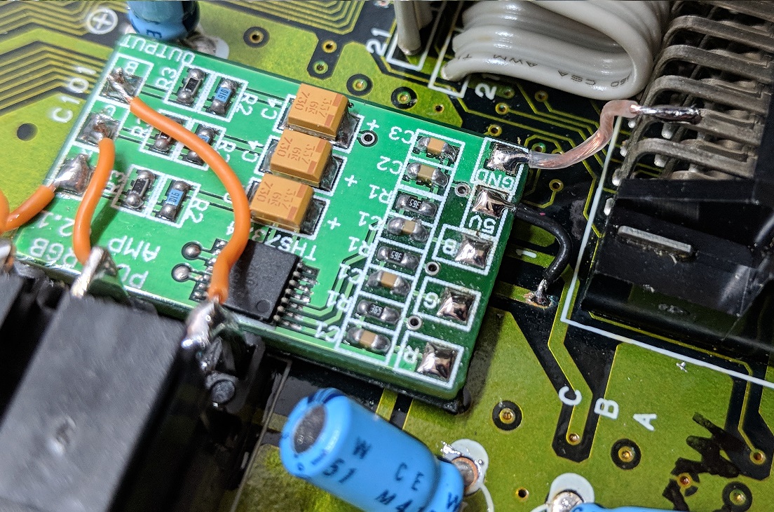
Solder the RGB wires to the bypass board. Make sure to keep track of which wire goes where so you don’t do what I did – red and blue are swapped in this picture.
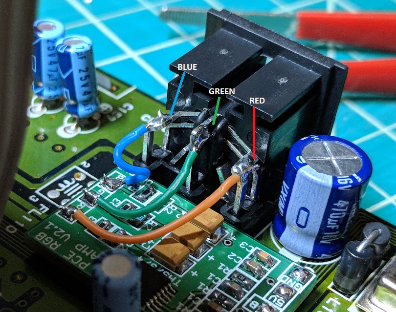
Solder wires from the bypass board to the rear pins of the DIN jack as shown. From left to right (looking at the back of the DIN jack), the connections are blue, green, and red. (Note: this picture shows the bypass board oriented backward from the rest of the guide, but the DIN locations are correct.)
Now just reassemble and enjoy!
