Tools
- 4.5 mm game bit
- Phillips screwdriver
- Soldering iron
PCE/CoreGrafx procedure
Although there are slight differences between the consoles, the procedure for getting at the guts should be largely the same.
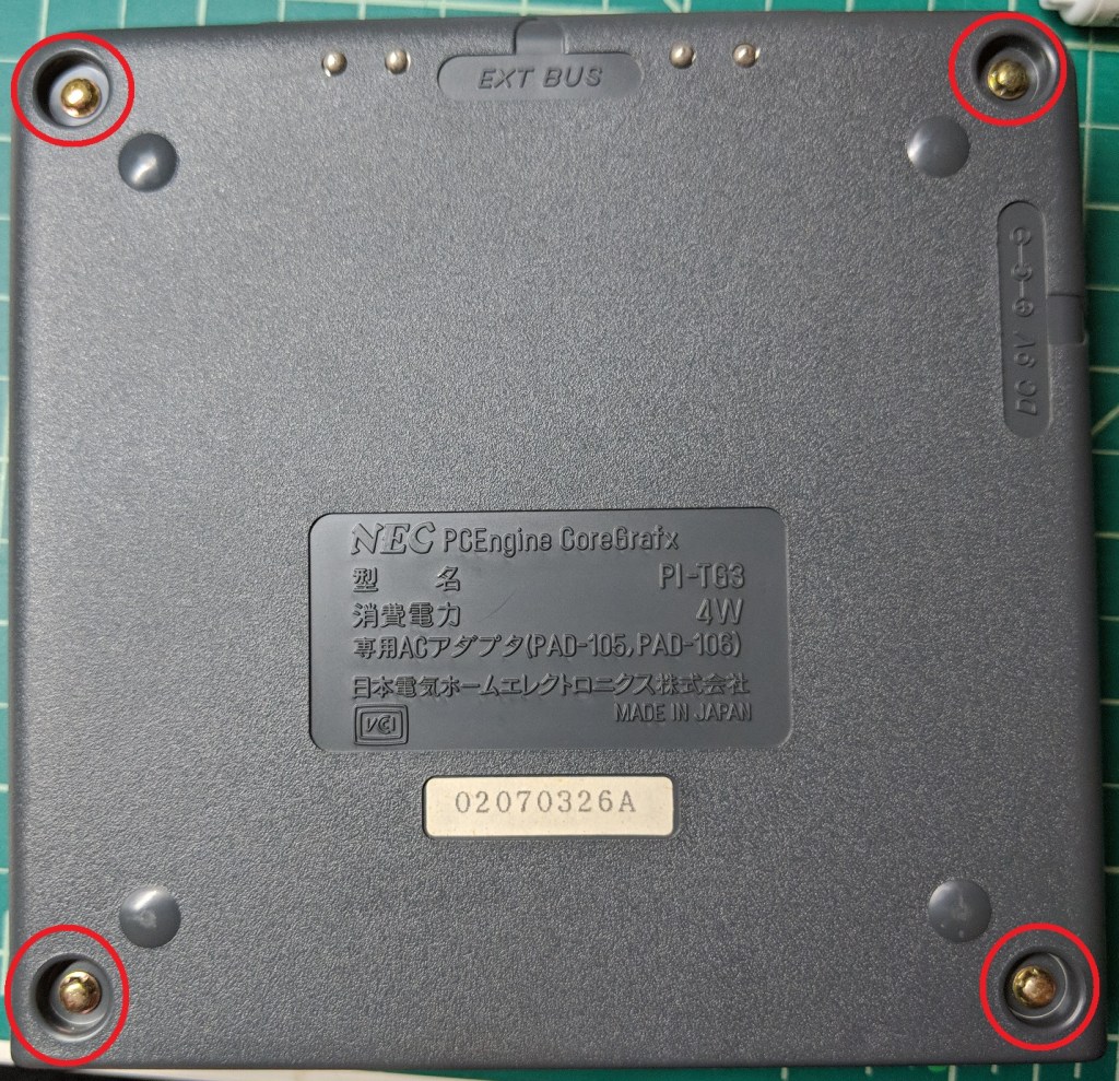
Flip the console over and remove these four screws using the game bit.
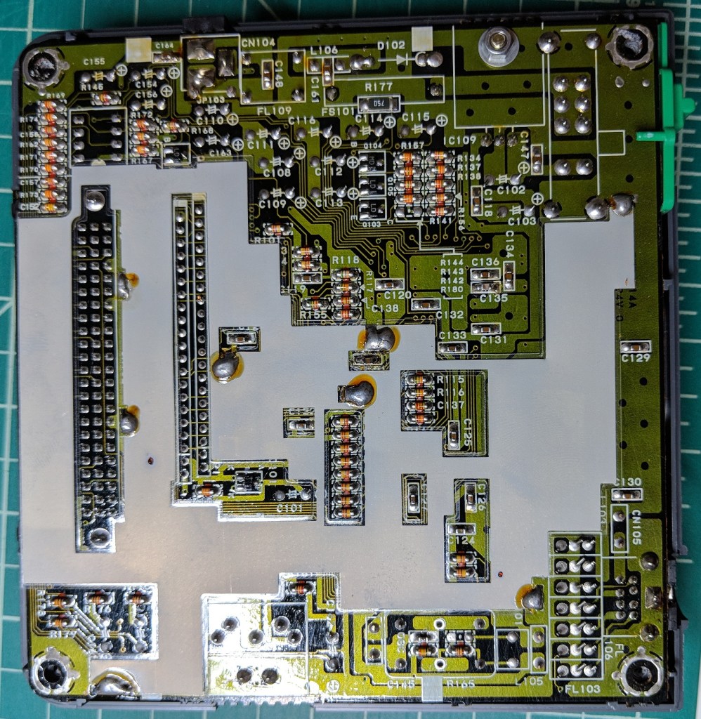
Pull up on the bottom of the case to remove it. It should come off easily. Once you have the bottom off, pull up on the motherboard to remove it from the case. In this picture, you can also see the shielding. This can be removed (if needed) by heating the solder points with a soldering iron while pulling up on the shield.
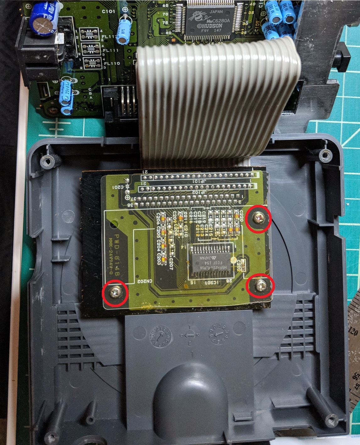
With the motherboard out of the way, you can see that it is connected to the HuCard slot via two large ribbon cables. To free the HuCard slot from the case, remove these three Phillips screws.
TurboGrafx-16 procedure
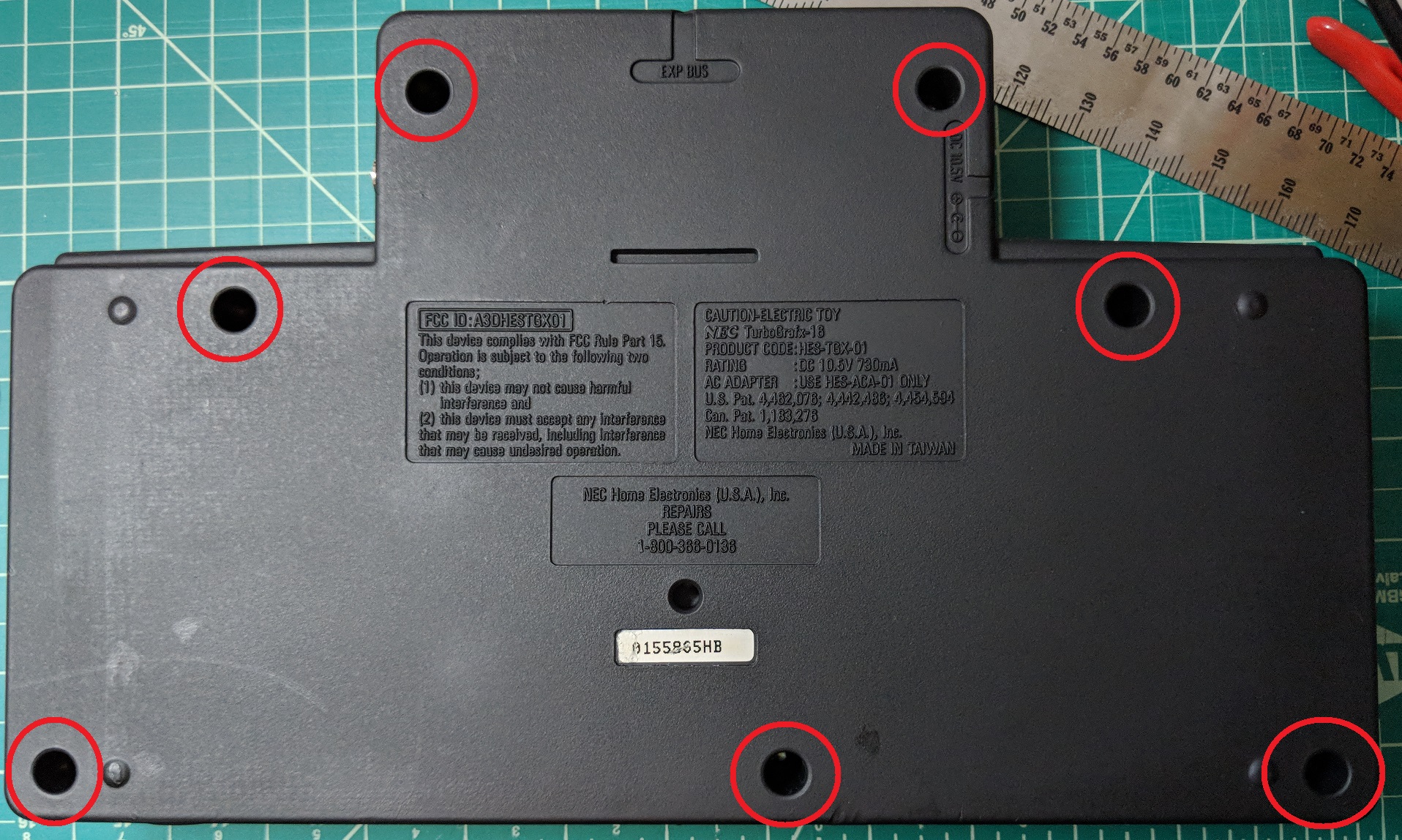
Flip the console over and remove these seven screws using the game bit.
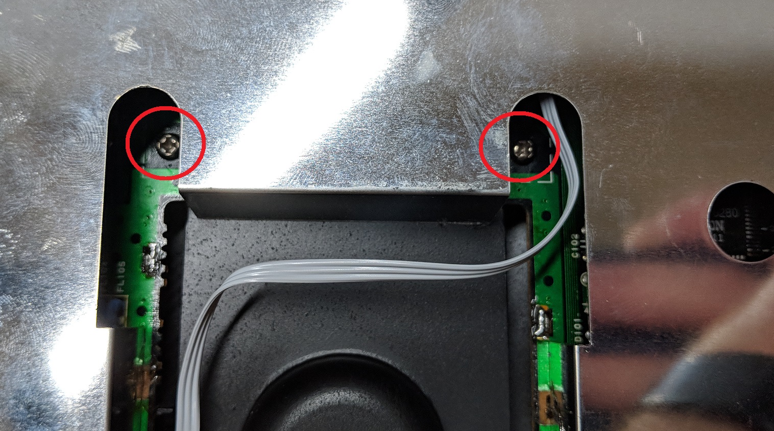
Pull up on the bottom of the case to remove it. It should come off easily. With the bottom out of the way, remove these two Phillips screws on either side of the HuCard slot. Ignore the wire in the photo, it is part of a region mod.
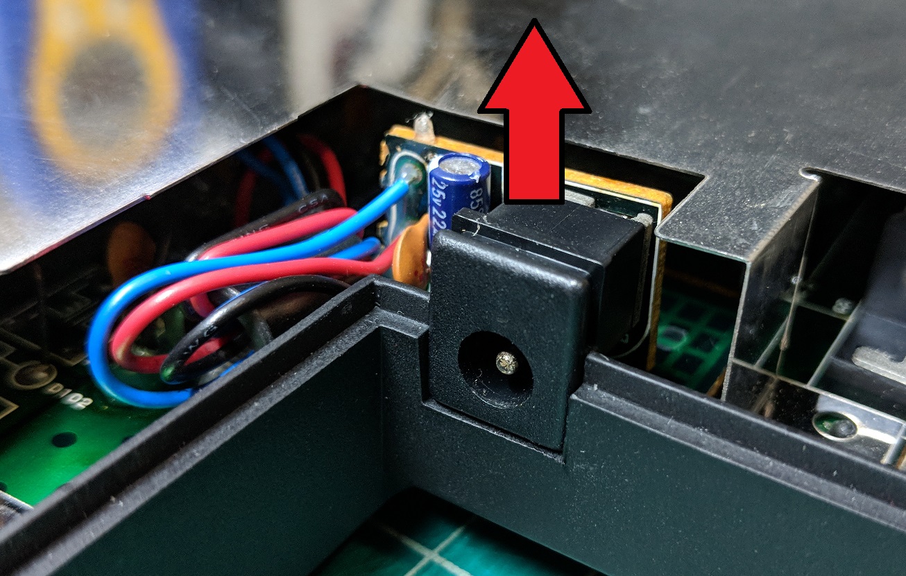
Pull up on the power jack to free it from the case.
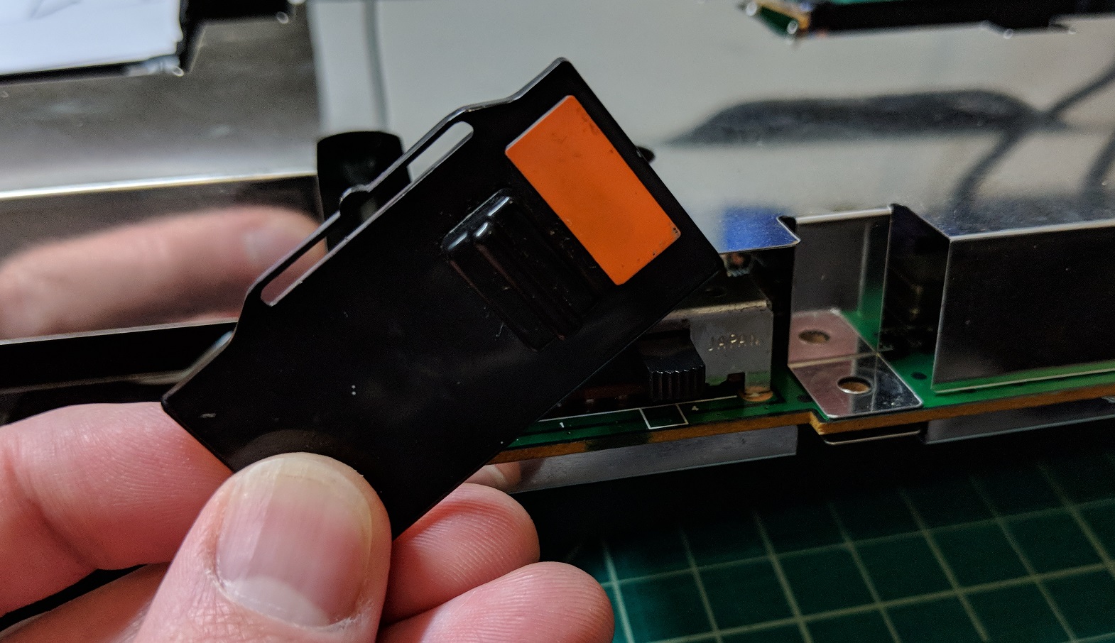
You should now be able to remove the guts from the case. I find it easiest to pull up from the back. The power switch cover (pictured) may fall off while you take the motherboard out, but, if not, I recommend pulling it off and setting it aside so you don’t lose it.
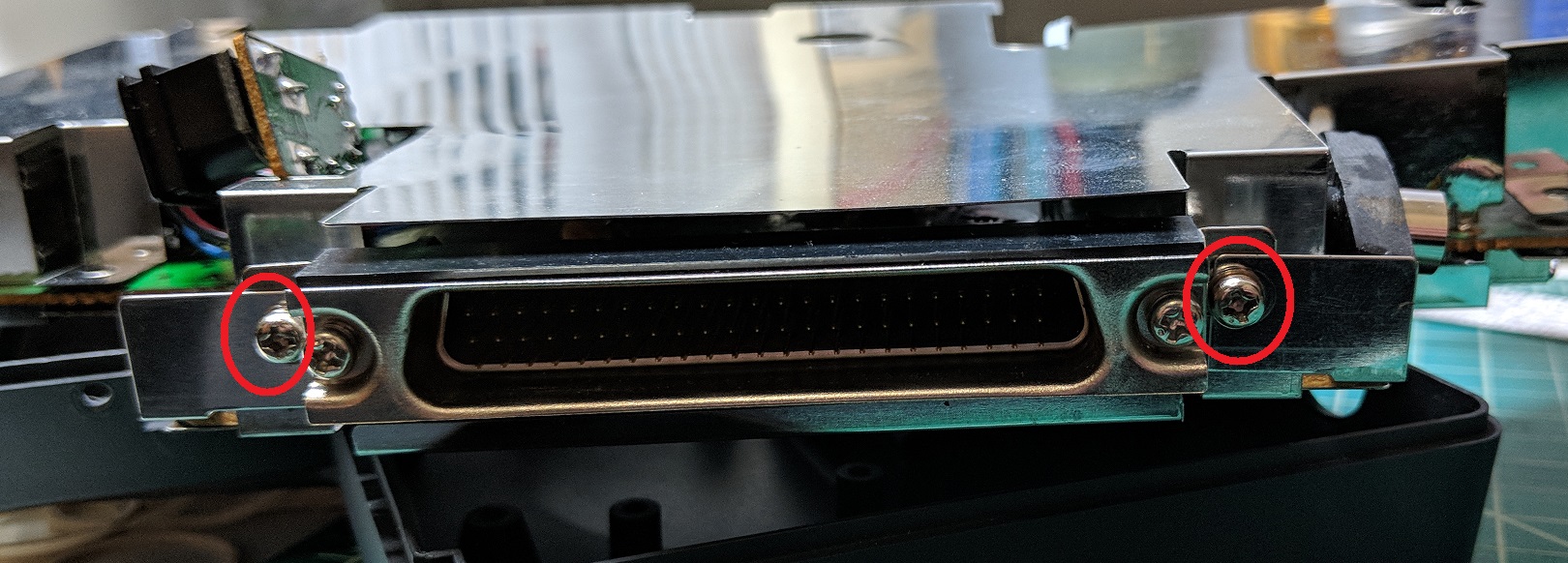
Remove these two Phillips screws from the back of the board.
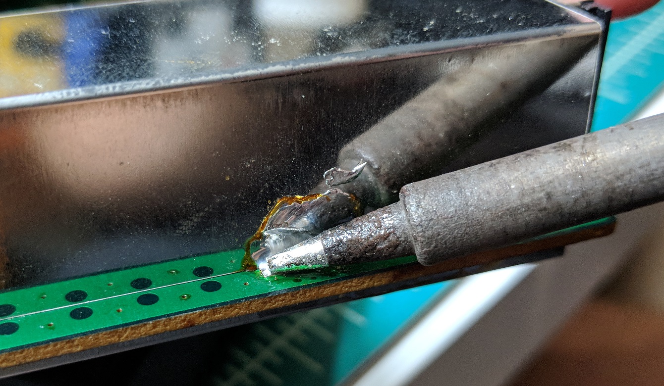
The RF shield is soldered directly to the circuit board. The solder pads aren’t very good, so don’t be surprised if some of them are broken. Some modders suggest just ripping the shield off, breaking the remaining pads in the process, but it’s pretty easy to remove the shield the right way. Just heat up the solder points with your soldering iron and, while the solder is fluid, pull up on the shield to free it from the motherboard. Keep going around until the upper shield is free.
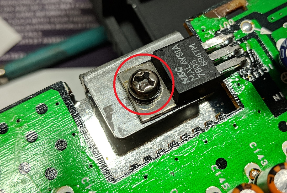
If you need to access the bottom of the board, remove the screw securing the power regulator to the heat sink and use the same procedure you used with the upper RF shield to free the lower shield.